
A workpiece-first evaluation guide for manufacturers and system integrators.
A toolpath can look feasible in CAD and still be difficult to execute on a real production part.
A formed flange may limit cutting-head access. A clamp can obstruct a contour. Variation between stamped parts may shift a critical feature. And a successful first cut does not necessarily prove repeatable production quality.
These are not reasons to reject robotic laser cutting. They are reasons to evaluate the application before choosing the machine.
Robotic laser cutting can be worth considering for trimming formed sheet metal, adding holes to curved surfaces, and processing certain irregular profiles. But the right approach depends on geometry, process requirements, tooling, and production conditions, not simply robot reach or laser power.
For manufacturers, engineering teams, and system integrators, six questions can make the initial assessment more useful.
01 / Does the part actually need 3D cutting?
Not every three-dimensional workpiece requires a robotic cutting cell. If the required cuts are accessible from one direction and lie predominantly in a single plane, a conventional 2D laser system may be simpler to implement. For other parts, cutting features may span formed flanges, angled faces, and curved surfaces.

The starting point is to map the cut features onto the actual part, rather than selecting equipment based on the part category alone.
Ask three things: Are features located on multiple faces? Must the cutting head approach at different orientations? Would a simpler cutting arrangement require additional repositioning or tooling?
A dedicated multi-axis machine may also deserve comparison, depending on the application. Robotic flexibility is valuable when it solves a specific access or changeover problem, not merely because it is available.
02 / Can the complete cutting tool follow the path?
A point may lie within a robot’s nominal working envelope while remaining impractical for cutting. The complete assembly matters: robot arm, cutting head, nozzle, cable routing, workpiece, and fixture.
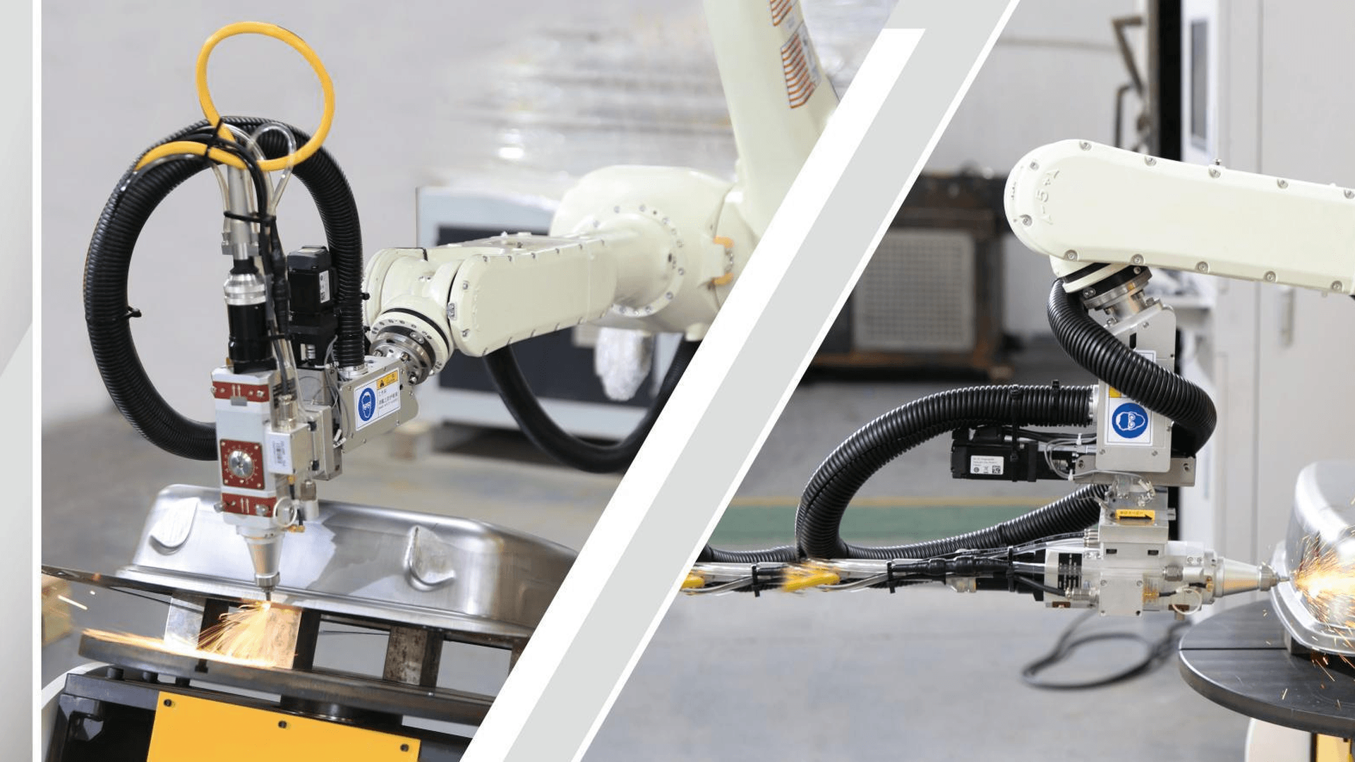
Evaluate the full toolpath, including approach, cutting motion, transitions, and retreat:
· Tool orientation: Can the head maintain a suitable angle to the local surface?
· Clearance: Is there enough space around flanges, openings, clamps, and nearby structures?
· Motion limits: Can the robot move through the path without undesirable configurations or joint-limit conflicts?
· Process distance: Can the required head-to-part relationship be maintained along the cut?
Offline programming and simulation can help identify reachability and interference issues, but a simulated path is not a substitute for checking the actual robot, cutting-head configuration, fixture, and part during physical trials.
Decision point: Verify the movement of the complete cutting system, not just the robot wrist.
03 / Have the material and cut requirements been defined?
A machine specification alone cannot tell you whether a particular cut will meet the drawing. Material grade, thickness, surface condition, feature geometry, and required edge quality all influence process development.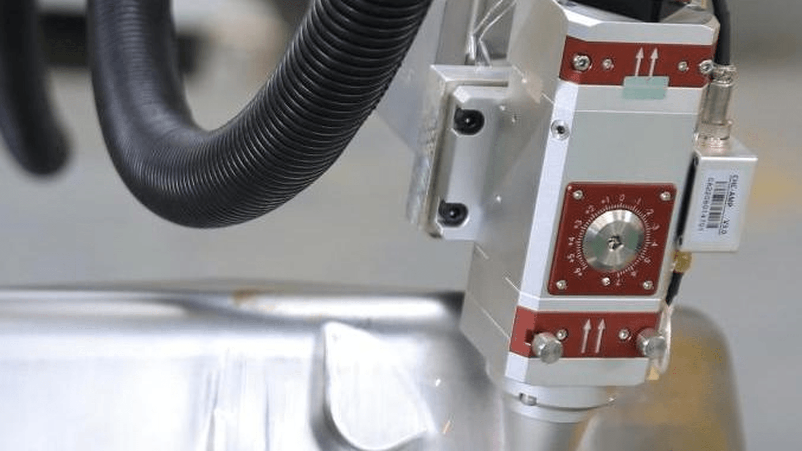
Before making a recommendation, document the essential inputs:
· Material and thickness range, including relevant coatings or surface conditions.
· Feature types: trimming, holes, slots, openings, bevels, or complex contours.
· Quality criteria: critical dimensions, edge condition, and downstream assembly needs.
· Process considerations: piercing, assist gas, focus, and cutting direction where relevant.
A cutting setup that works for one part should not automatically be assumed suitable for another. Trials using representative material and geometry are often the most reliable way to determine whether the proposed process deserves further development.
Decision point: Evaluate the actual material-feature combination instead of relying on a headline power rating.
04 / How repeatably can the part be located?
The fixture is part of the cutting process. Even if the robot repeats its programmed motion, variation in part position can change where that path meets the metal.
This is especially relevant for formed and stamped components. Springback, upstream manufacturing variation, and inconsistent locating surfaces may affect the position of holes, edges, and trimmed contours.
A practical workholding review should address four questions:
· Which datums locate the part, and are they repeatable?
· Do clamps hold the part securely without obstructing required cuts?
· How will dimensional variation between incoming parts be handled?
· What changes when another part number enters the cell?
Robot positioning repeatability and finished-part cutting tolerance are different measures. Fixturing, process conditions, and measurement are needed to assess the actual result.
05 / What does flexibility require in programming and changeover?
Robotic cutting can provide options for different workpiece shapes, but production flexibility is not free of engineering effort. New parts may require revised toolpaths, fixture adjustments, clearance checks, and process validation.
Depending on the supplied system and software configuration, paths may be prepared through offline programming, robot teaching, or a combination of methods.
A practical preparation sequence is:
1. Review the CAD model and mark critical cutting features.
2. Plan head orientation and generate or teach the robot path.
3. Check reachability, fixture clearance, and path transitions.
4. Carry out representative cutting trials and adjust parameters.
5. Confirm the program and changeover method before production release.
For high-mix manufacturing, ask how much work is required for the second and third part, not only the first. The relevant measures may include programming time, tooling changes, operator involvement, and achieved cycle time.
Decision point: Judge flexibility by the effort needed to launch the next part reliably.
06 / What will prove the cut is production-ready?
A successful demonstration cut shows that the process can work under specific conditions. Production readiness requires an agreed method for checking results and consistency.
A useful acceptance plan examines three layers of evidence:
· Cut condition: Check edges, burrs or dross, holes, slots, contours, and any defects relevant to the application.
· Dimensional conformity: Measure critical feature sizes and locations against the approved drawing and tolerance requirements.
· Repeatability and production fit: Evaluate multiple representative workpieces, then review cycle time, changeover effort, and inspection needs.
The sample plan, inspection method, and pass/fail criteria should be agreed before drawing conclusions. An attractive cut edge in a photograph cannot replace dimensional evidence, and robot repeatability is not the same as workpiece accuracy.
For System Integrators: Define the Project Boundary Early
For equipment partners, the technical review should also clarify who is responsible for each interface. The exact scope varies by project, so it is important not to assume that every supplier provides a complete production line.
Typical points to agree include the supplied equipment and programming functions; fixture design and workholding; control and plant interfaces; laser safety measures, guarding, and extraction; commissioning responsibilities; and operator training or technical support.
A clear division of responsibilities makes the proposed solution easier to assess and reduces uncertainty during implementation.
Start with the Workpiece, Not the Machine Brochure
The most useful initial discussion is usually based on a real application. A 3D drawing or marked-up part photo, the material and thickness, target features, quality requirements, expected production volume, and any known fixturing constraints can help define the next engineering questions.
At Xunchi, we work on laser automation applications, including robotic laser cutting. Our starting point is to understand the component and processing requirements before considering an appropriate equipment configuration and validation approach.
Evaluating a complex 3D cutting part? Share the application details that you are able to disclose and let’s discuss the technical feasibility and next evaluation steps.
Xunchi | Laser Automation Solutions Provider
Email: info@xunchitech.net
Website: www.xunchitech.net


